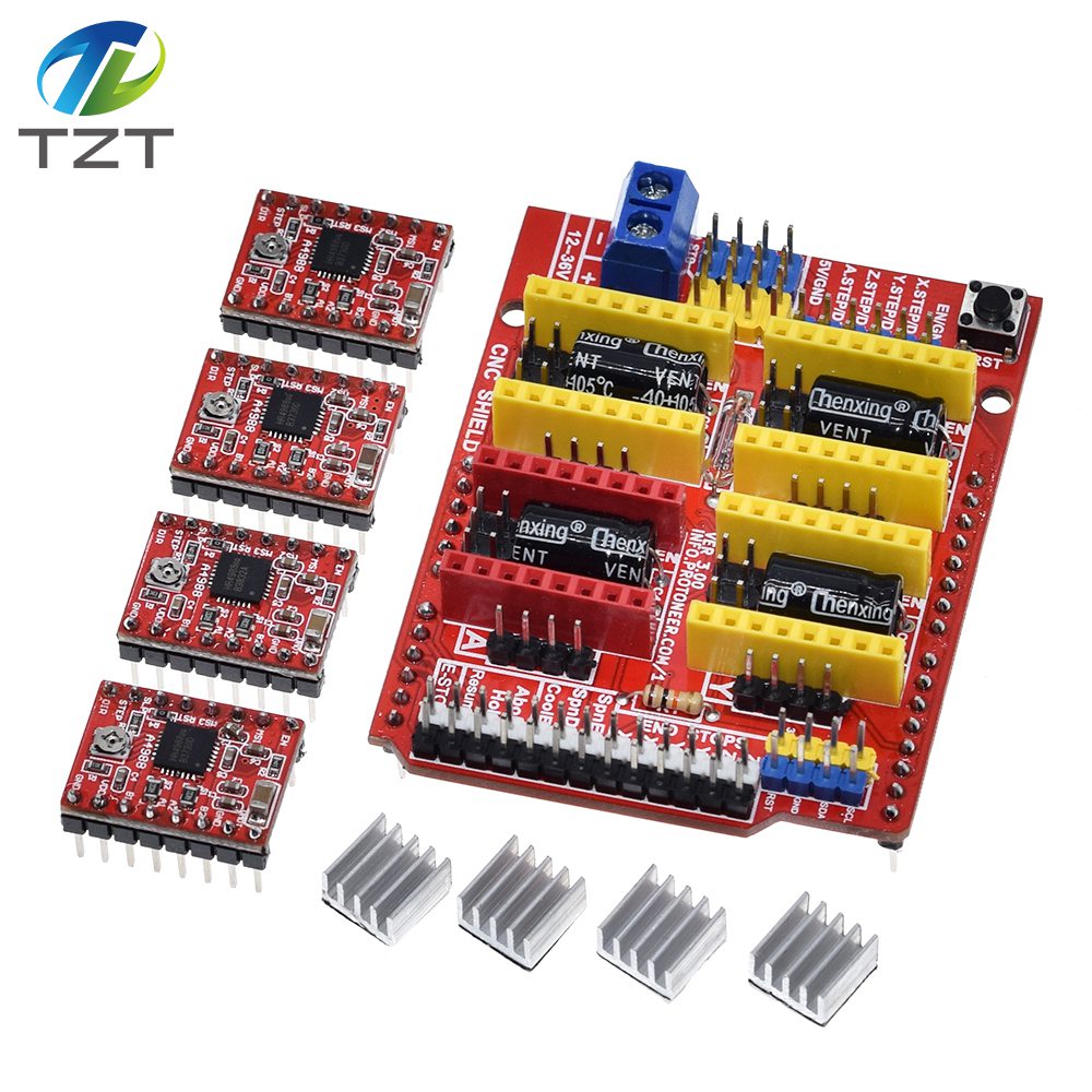
Introduction
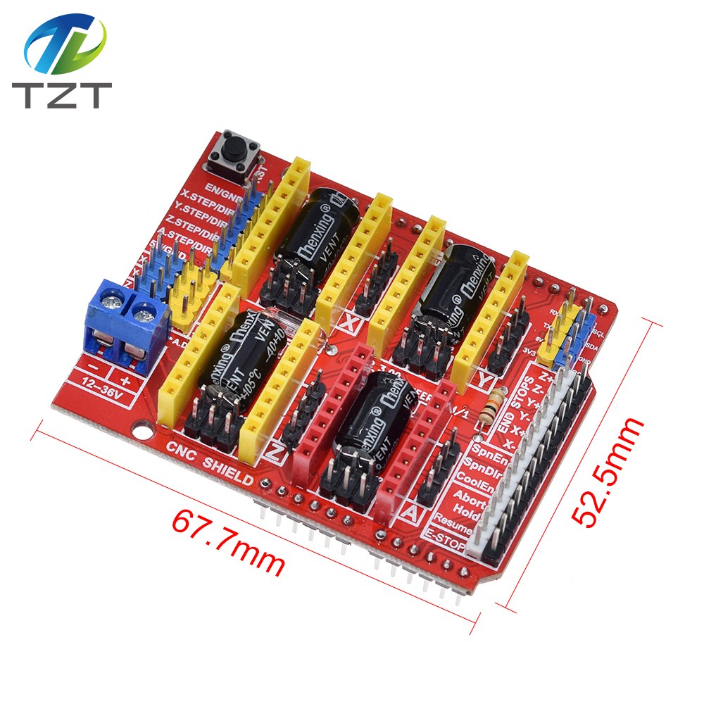
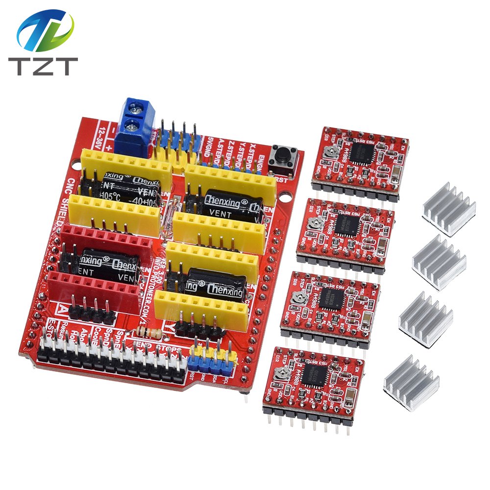
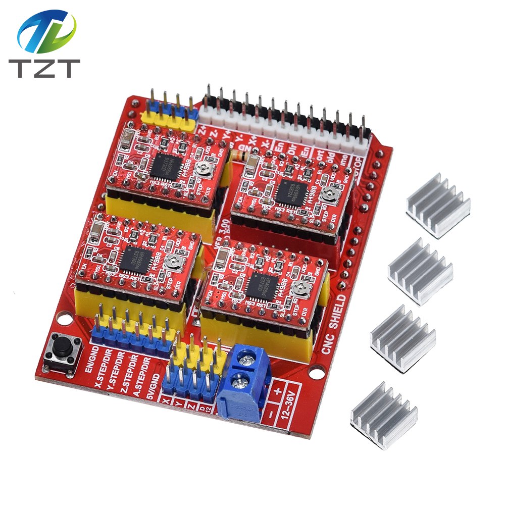
This expansion board as a driver expansion board, can be used
for engraving machines, 3D printers.
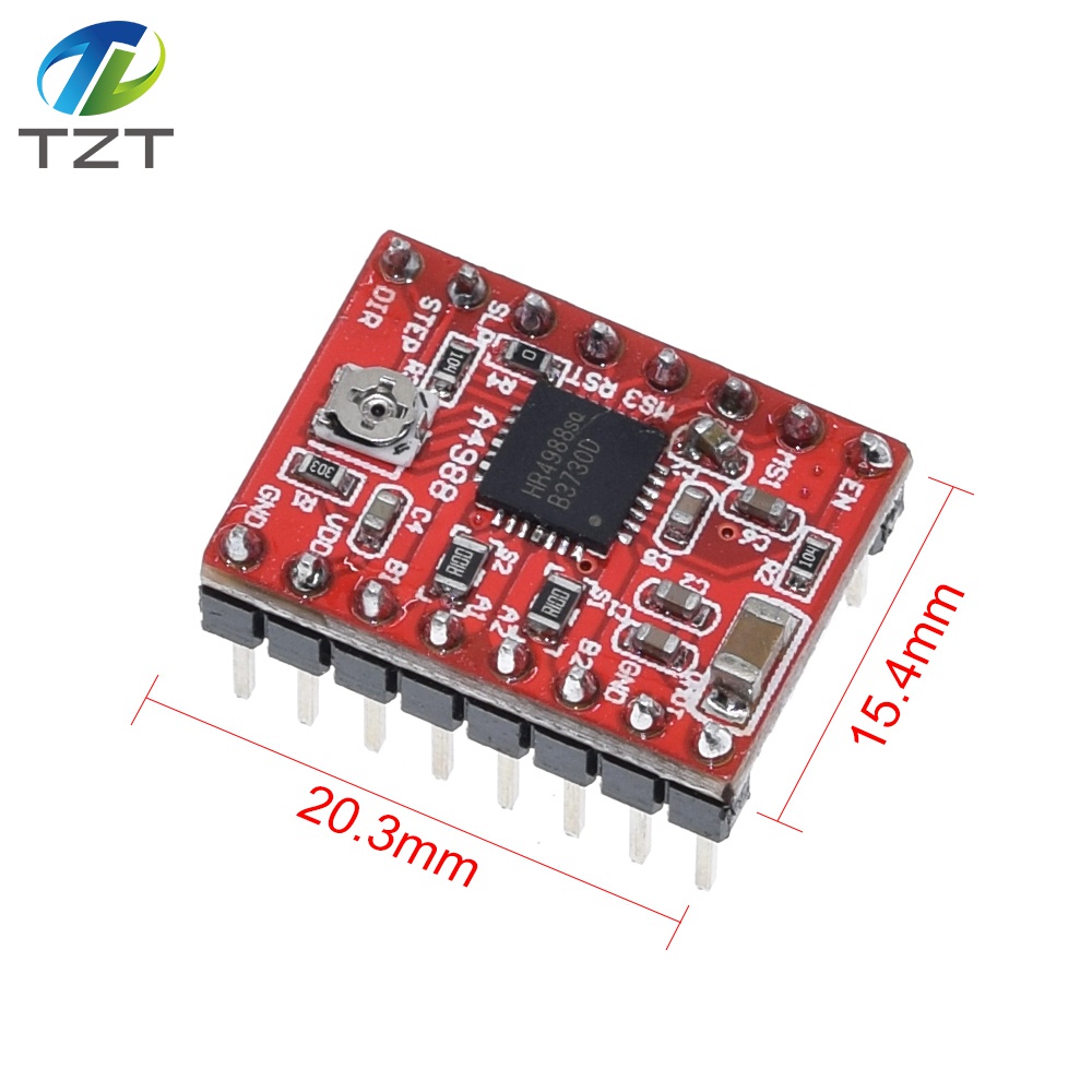
It is a total of four slots, can drive
four A4988 stepper motor. Each road stepper motors only need two IO ports. In
other words, six IO ports can be well managed three stepper motors. Very
convenient to use.
Two, UNO for module IO port correspondence
introduction.
IO corresponding figure above
UNO---------------------
expansion board
8 ------------------------ EN ( stepper motor driver enable ,
active low )
7 ----------------------- Z.DIR (Z -axis direction control
)
6 ----------------------- Y.DIR (Y -axis direction control )
5
----------------------- X.DIR (X -axis direction control )
4
---------------------- Z.STEP (Z -axis stepper control )
3
---------------------- Y.STEP (Y -axis stepper control )
2
---------------------- X.STEP (X -axis stepper control )
/ / The
following is a simple stepper motor control procedures,
# define EN 8 / /
stepper motor enable , active low
# define X_DIR 5 / / X -axis stepper motor
direction control
# define Y_DIR 6 / / y -axis stepper motor direction
control
# define Z_DIR 7 / / z axis stepper motor direction control
#
define X_STP 2 / / x -axis stepper control
# define Y_STP 3 / / y -axis
stepper control
# define Z_STP 4 / / z -axis stepper control
/ *
/ /
Function : step . function: to control the direction of the stepper motor , the
number of steps .
/ / Parameters : dir direction control , dirPin
corresponding stepper motor DIR pin , stepperPin corresponding stepper motor "
step " pin , Step number of step of no return value.
* /
void step
(boolean dir, byte dirPin, byte stepperPin, int steps)
{
digitalWrite
(dirPin, dir);
delay (50);
for (int i = 0; i
digitalWrite (stepperPin,
HIGH);
delayMicroseconds (800);
digitalWrite (stepperPin,
LOW);
delayMicroseconds (800);
}
}
void setup () {/ / The stepper
motor used in the IO pin is set to output
pinMode (X_DIR, OUTPUT); pinMode
(X_STP, OUTPUT);
pinMode (Y_DIR, OUTPUT); pinMode (Y_STP, OUTPUT);
pinMode
(Z_DIR, OUTPUT); pinMode (Z_STP, OUTPUT);
pinMode (EN,
OUTPUT);
digitalWrite (EN, LOW);
}
void loop () {
step (false,
X_DIR, X_STP, 200); / / X axis motor reverse 1 ring, the 200 step is a
circle.
step (false, Y_DIR, Y_STP, 200); / / y axis motor reverse 1 ring, the
200 step is a circle.
step (false, Z_DIR, Z_STP, 200); / / z axis motor
reverse 1 ring, the 200 step is a circle.
delay (1000);
step (true, X_DIR,
X_STP, 200); / / X axis motor forward 1 laps, the 200 step is a circle.
step
(true, Y_DIR, Y_STP, 200); / / y axis motor forward 1 laps, the 200 step is a
circle.
step (true, Z_DIR, Z_STP, 200); / / z axis motor forward 1 laps, the
200 step is a circle.
delay (1000);
}


China (Mainland)
 TUOZHANTENG electronic components Co., LTD
 0755-82527072
 emily@tztstore.com
 3013 Hongli Road, Shanghang Building 5F/511, Huaqiangbei , Futian , Shenzhen , Guangdong , China.
Hong Kong,China
TUOZHANTENG HK CO., LTD
1244995775@qq.com
Room 1103, Hang Seng Mongkok Building, 677 Nathan Road, Mongkok, Kowloon, Hong Kong
WhatsApp +86 15920041318
![]() WeChat +86 15920041318
WeChat +86 15920041318
Telegram/ KakaoTalk :+86 15920041318
Website customer service

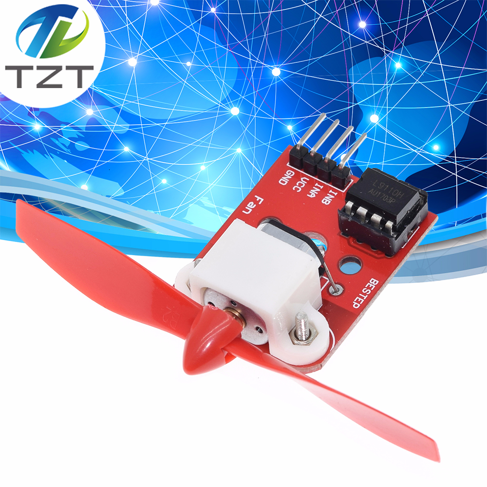
5V L9110 Fan Motor Module Fan Propeller Firefighting Robot For Arduino DIY
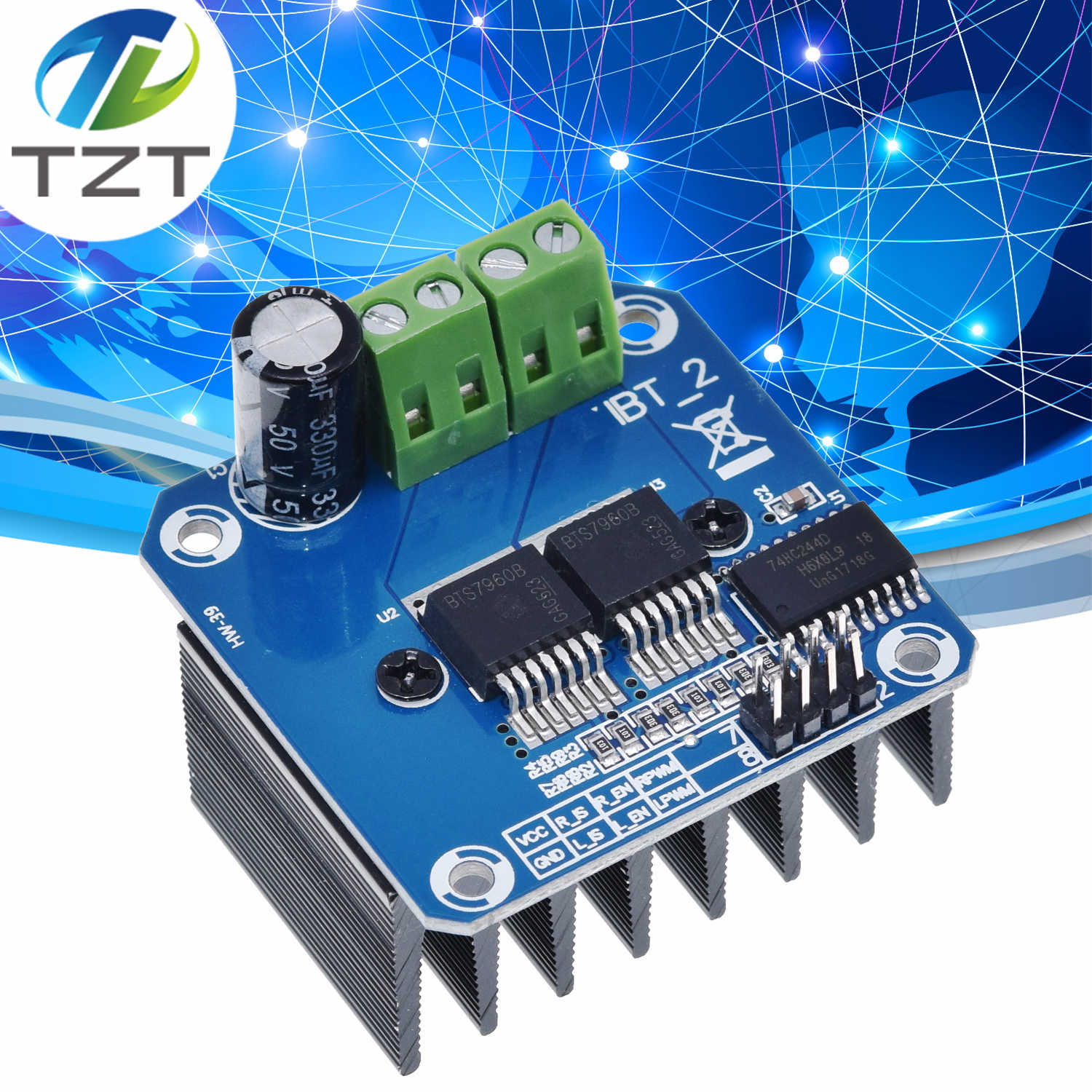
TZT Double BTS7960 43A H-bridge High-power Motor Driver module / diy smart car Current diagnostic for Arduino
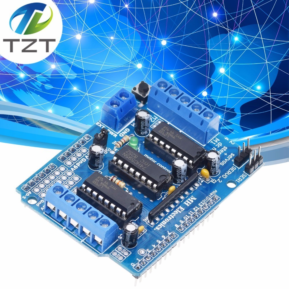
TZT L293D motor control shield motor drive expansion board FOR Arduino motor shield
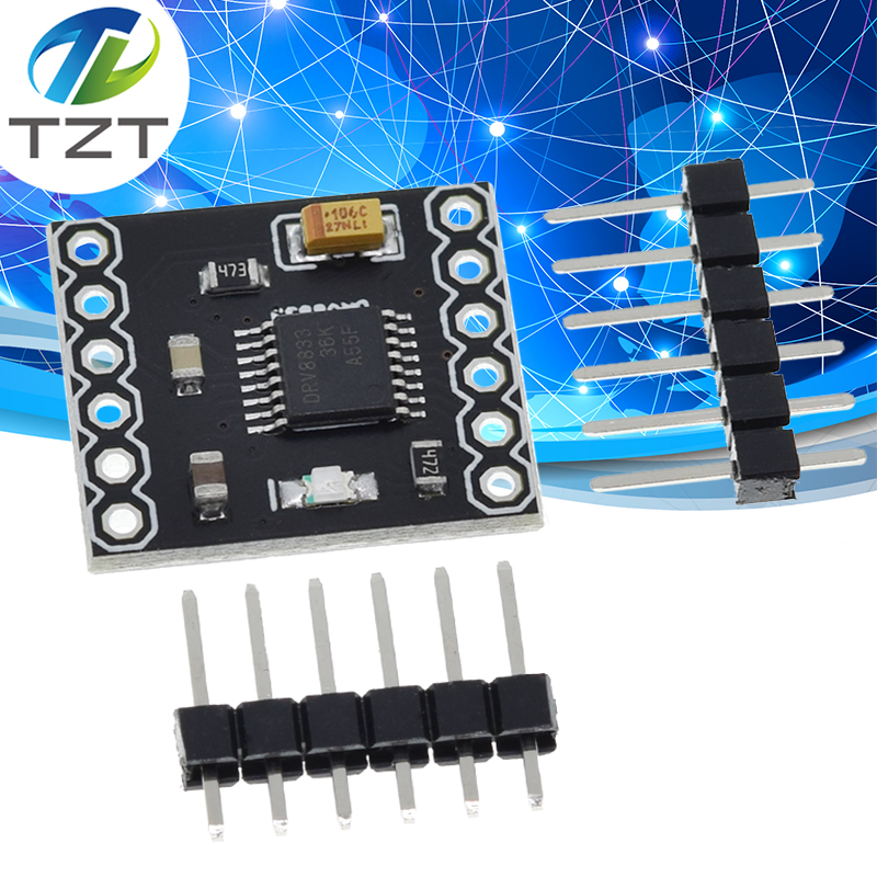
DRV8833 2 Channel DC Motor Driver Module Board 1.5A 3V-10V H-Bridge 4-Wire Step Motor Overcurrent Protection Step Motor Drive
DRV8833 2 Channel DC Motor Driver Module Board 1.5A 3V-10V H-Bridge 4-Wire Step Motor Overcurrent Protection Step Motor Drive
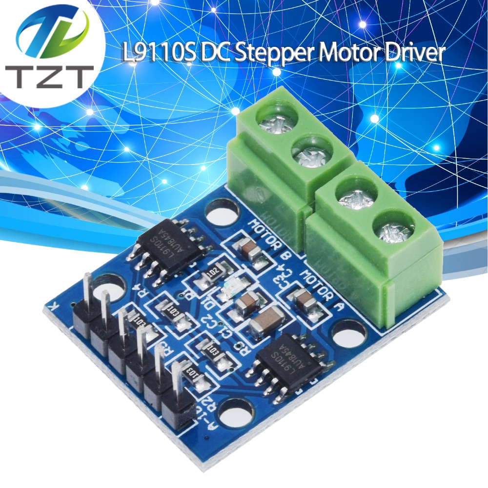
L9110S H-bridge Stepper Motor Dual DC Stepper Motor Driver Controller Board Module L9110S L9110 For Arduino
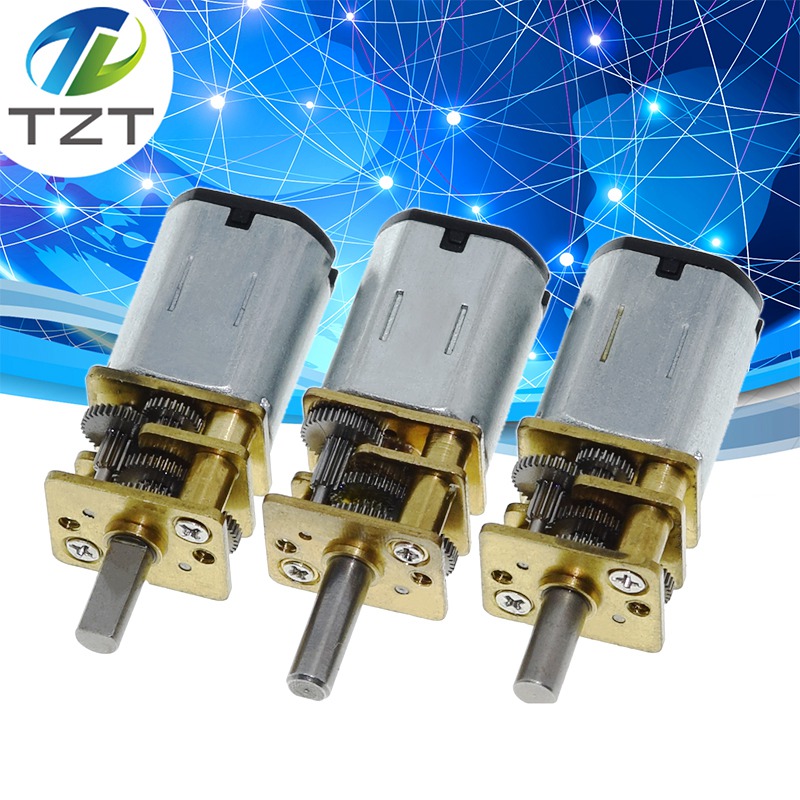
GA12-N20 DC 6V 30RPM 100RPM 200RPM Gear Motor Speed Reduction Gear DC Motor Electric Gear Box with Gearwheel for RC Robot DIY
GA12-N20 DC 6V 30RPM 100RPM 200RPM Gear Motor Speed Reduction Gear DC Motor Electric Gear Box with Gearwheel for RC Robot DIY
Tel